Schedule a Call Back
Helical Gears
Helical Gears
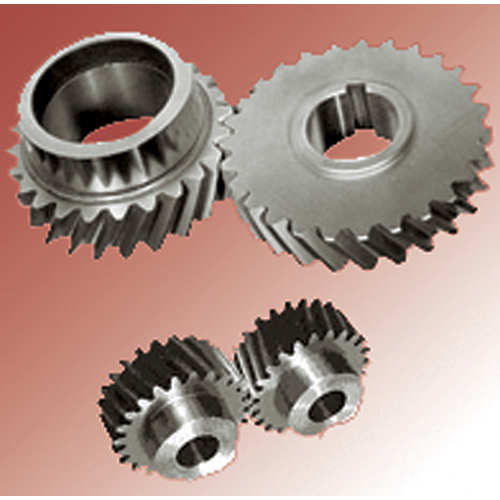
J V Engineers’ Helical Gears offer a refinement over spur gears. The leading edges of the teeth are not parallel to the axis of rotation, but are set at an angle. Since the gear is curved, this angling causes the tooth shape to be a segment of a helix. Helical gears can be meshed in a parallel or crossed orientations. The former refers to when the shafts are parallel to each other; this is the most common orientation. In the latter, the shafts are non-parallel. The angled teeth engage more gradually than do spur gear teeth causing them to run more smoothly and quietly. With parallel helical gears, each pair of teeth first make contact at a single point at one side of the gear wheel; a moving curve of contact then grows gradually across the tooth face to a maximum then recedes until the teeth break contact at a single point on the opposite side. In spur gears teeth suddenly meet at a line contact across their entire width causing stress and noise. Spur gears make a characteristic whine at high speeds and cannot take as much torque as helical gears; whereas spur gears are used for low speed applications and those situations where noise control is not a problem, the use of helical gears is indicated when the application involves high speeds, large power transmission, or where noise abatement is important. The speed is considered to be high when the pitch line velocity exceeds 25 m/s.


