Schedule a Call Back
Robotics: fundamentals, principles of working & components
 Technical Articles
- Nov 30,-1

Robots are today invading the shop floor like never before. Dr K C Jain explains the basics of robots and robotics in this two-part article.
A robot is an electro-mechanical machine or artificial intelligent machine guided by a computer program. The Robot Institute of America and Robot Industries Association defines robot as a “programmable, multi-function manipulator designed to move material, parts, tools or special devices through variable programmed motions for the performance of variety of tasks”. In simple words, it is a machine with a degree of artificial intelligence, operated under the control of a mini or micro-computer.
Robotics is an element of the science of automation. It uses machines intelligence, which can be taught to compensate for varying conditions of operation. The term robot is traced from Czech word robota, for “servitude,” “forced labour” or “drudgery”, or in other words menial unpleasant work. The term first appeared in 1921 in the play R.U.R (Rossum’s Universal Robots) by Czech dramatist Karel Capek.
Advanced robots were first attempted after the development of the computer. In the late 1960s, the Stanford Research Institute designed and built an experimental robot called SHAKEY using a television camera and a computer. This machine was capable of palletizing blocks into stacks.
General Motors financed a program at the Massachusetts Institute of Technology in mid-1970s to develop an automated robot for assembly purposes. Here Victor Sheinman invented the PUMA (Programmable Universal Manipulator for Assembly), thus the entry of robots into American industry began; very soon it entered the rest of the world. Use of robots has shown marked importance in the field of manufacturing automation.
The details of an industrial robot are as follows:
Industrial robots are required perform a wide range of tasks such as spot and arc welding, pick ‘n’ place activities, etc. Figure 1 shows the basic parts of an industrial robot.
Kinematics of robotic system
In all essential aspects a robot resembles perfectly the human arm in appearance structure and in many of its functions. In order to understand the robotics system, see Fig. 2a. This figure is self explanatory to understand the robotic arm and human system similarities.
The human arm consists of two distinct parts: the wrist with three minor joints, and the arm’s two major joints, i.e., the shoulder and the elbow. The function of the human wrist is to provide the orientation of the object held by the hand. Various functions of the arm may be explained as follows:
>> Hold your right arm and hand straight out. Keeping the palm in downward direction, this is the reference angular position (0o). Then rotate your wrist as far in both clockwise and anticlockwise directions. This is called roll motion and limits of rotation as -180o and +90o respectively, i.e., Roll (angle) = 180o – 0o – (-90) = 270o.
>> Again holding the right arm in the reference position (0o) and without rolling the hand. Move the wrist from the initial straight position as far as possible in a downward and then in an upward direction. Called pitch motion and its limit positions are at – 90o and 50o, i.e., Pitch (angle) = 90o – 0o – (- 50) = 140o
>> Holding your right arm straight out and the wrist making neither a roll nor a pitch motion. Let the fingers point horizontally as far as possible to the right and then to the left. This is the yaw motion and its limit positions are at – 45o and + 15o, i.e., Yaw (angle) = + 45o – 0o – (- 15) = 60o
Roll, pitch and yaw are considered independent motions and therefore referred to as degrees of freedom.
The second part of the human arm has two major joints with three degrees of freedom, two in the shoulder and one in the elbow. But the robot has a shoulder with one degree of freedom only, and thus the robot waist is introduced as a substitute for one of the shoulder’s independent motions. In the case of a human the waist has a different function, i.e., it is for manoeuvrability by counter-balancing the human body against the gravitational load in changing body postures. The counter balance in robots is some time used by incorporating a mechanical loop in its structure.
The human arm has five fingers with three degrees of freedom in each one of them. These fingers are used to grip a part of any configuration either in conjunction of each other or individually independently depending on type of job, object to be handled and degrees of freedom to be used. The fingers are used independently with dexterity; contrary to this, the robot gripper has independent mobility and no dexterity except for very rare tasks.
In 85% of pick-n-place industrial robots, the gripper does not have more than two or three fingers because in industrial work only the thumb, first and middle fingers are used.
An important feature of the robot structure is the ratio of the length of upper arm to that of the fore arm, which is around 1.2. This implies that robot’s forearm should be either equal to or slightly shorter than the upper arm. If this rule is not followed there will be robot performance impairment. Remember, the robot is a mechanical system representing human arm, however, it cannot reach the human arm’s performance capabilities as this consists of large scale hierarchical system composed of large number of linear and non linear elements.
Different parts of a robot:
Referring to Fig 2(a) and (b) it is observed that a mechanical robotic system should possess an many as possible the following elements:
>> Controller
>> Manipulator
>> Gripper or end effector
>> Power supply or energy source, and
>> Data acquisition system (vision sensors system).
Remember that robots are devices that imitate human manipulation; however, these are built by people, programmed by people and maintained by people, hence they are what they have been made by them.
Controller: Type and classification
The controller is much like the human brain which coordinates the muscles and all other parts of the body. It keeps track of time, the position of the joints, and the movements of the manipulator. It does this as per programme and with a list of instructions. The instructions are stored in the memory unit of controller. The control unit can be further classification as mechanical, pneumatic, or electrical.
Unlike the human brain, the controller is not capable of the intuitive thinking necessary for adaptive behaviour. All movements must be stored in its list of instructions, it cannot cope with environmental input such as a robot can draw a picture but it cannot create an original drawing.
A controller in a modern reference is a computer that stores the robot’s program and controls the robot’s motions by communicating with the actuation mechanism.
Classification of controllers:
>> Mechanical type
>> Pneumatic or air logic type
>> Hydraulic type, and
>> Electrical/electronic type, i.e., (a) Programmable controller microcomputer type, b) Micro process based, and (c) Minicomputer based controller.
Detailed description of the above mentioned types of controllers is as follows:
Mechanical or cam logic type controller: The early robots were point to point motion devices and were used in robotic systems. It was not possible to programme them. The purpose of robot arm control was to maintain the dynamic response of the manipulator as per the pre-specified objective through mechanical linkage and cam.
Pneumatic or air logic controller: Such controller is used for pick and place robots, where the simplicity of the tasks to perform is the low cost advantage of the robot. There is absolutely no fire or pollution hazard from this type of robot.
The normal air that factory employees breathe is drawn in from around compressor site. It is dried, filtered and lubricated after compression.
Hydraulic type system: This type of controller is used for robots that must move large or heavy loads. Such loads rarely need to be placed with extreme accuracy, e.g., stacking and palletizing might be tasks included in this group.
Electrical or electronic type: This type of control is convenient, clean, quiet, reasonably fast, and used on nearly all assembly robots that require close tolerance accuracy. Their power/weight ratio is being continually improved, as is their speed/weight ratio. These improvements are due to new configurations and materials and the use of direct-drive motors.
Programmable controller: It is like the mechanical or pneumatic logic type controller for point to point pick and place function, but this function is obtained through a programme.
Micro process based controller: This type of controller uses a 16-bit or 32-bit microprocessor and works as a multiprocessor system for coordinate transformation or dynamic compensation of the robot arm. Such a controller ensures proper execution of manipulator for attaining the sequences defined by the programme.
Mini computer based controller: In such a controller the output from a small, computer is fed in to a specialised electronic control circuit to control the installed, robot’s manipulator. The example of such a controller is computer control of a blast furnace.
Manipulator: The manipulator in the present case is the entire mechanism of the robot that provides movement of any degree of freedom. Therefore it consists of base, arm and gripper.
Grippers and end effectors: The gripper is similar to the human hand. Just as the hand grasps the tool to perform the work, the gripper secures the robot’s work piece while the operation is being performed. The shape of the gripper is determined by the task it has to perform. Two-pronged or general grippers are used to pick up cylindrical and cubic objects. Three-pronged grippers are used on spherical objects, and specialised grippers can be designed for unique tasks. Some grippers are equipped with a sense of touch also.
Sensors
If robots are to become more effective for industrial work and other tasks these must be provided with the ability to ‘see’ and ‘to feel’.
For almost all industrial robots visual and feel, i.e., ‘touch’ information, if provided will suffice to a greater extent of artificial intelligence to robots which will include distance, orientation, shape, surface, etc. Thus provision of sensors on robots will equip them with greater degree of decision making capability. (For different types of sensors see Fig. 3).
Source of Power and Drives
There are three types of sources of power devices for robotic systems. These are: pneumatic; hydraulic or electro hydraulic; and electric.
>> Pneumatic power is source used for pick-n-place robots where simple tasks are to be performed by the robot at low cost of operation.
>> Hydraulic drives are used for heavy loads with no absolute accuracy, e.g., stacking and palletizing task, paint spraying and gluing.
>> Electric power drives are quite clean, quiet, reasonably fast and are used for robots that require close tolerance accuracy. Use of direct drive motors on robots improve power/weight and speed/weight ratio.
– Dr K C Jain
References:
1. Chirouze & others: An Introduction to Robot Technology. New York, McGraw Hill 1984-85.
2. Compton: Understanding Robots. USA, Alfred Publishing Co Ltd 1983.
3. Heer E: Robots and Manipulators, “Mech Engg” Nov. 1981, pp. 42-39.
4. Liptak K, Robotics Basics. New Jersey, Prentice Hall 1984.
Related Stories

Indian manufacturing sector: Negotiating its way in a less VUCA world
India’s manufacturing sector is evolving through policy support, technology adoption and sectoral growth, though challenges in R&D and skilling remain, writes Prof R Jayaraman, Head, Capstone Proj..
Read more
Manufacturing Strength Behind India’s Self-reliance and Global Positioning
India’s manufacturing sector is evolving from domestic self-reliance to global leadership, navigating a VUCA environment through strategic policy, capability building and infrastructure-led execut..
Read more
India’s Manufacturing Reset in an Uncertain World
Global manufacturing is being reshaped by volatility and disruption. This release outlines how India is strengthening depth, resilience and capability to emerge as a long-term manufacturing partner,..
Read moreRelated Products
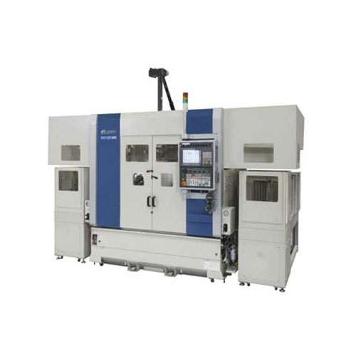
Compact Fmc - Motorum 3048tg With Fs2512
Meiban Engineering Technologies Pvt Ltd offers a wide range of Compact FMC - Motorum 3048TG with FS2512.
Structural Adhesive for Solar Panel Roof Mounting
Parson Adhesives India Private Ltd offers a wide range of structural adhesive for solar panel roof mounting – Partite 7535.
Industrial Tsn Switch
Contec launches a future-ready Industrial TSN Switch- SH-9210TSN.


