


Schedule a Call Back


Machine Vision Inspection of Heat Exchanger Block
 Technical Articles
- Feb 07,13
NULL


Machine vision is a part of Artificial Intelligence process and has emerged as one of the trustworthy technologies for various applications. The technology surfaced in 1990s, but actual applications are built now with advent of many faster technologies for cameras and processing devices. Any practical industrial application involving machine vision technology requires understanding of various areas like image processing, optics, electronics, cameras, automation and also mechanical handling system. Even though very high level of knowledge base is not required in all the streams mentioned above, the failure of any one stream leads to failure of system as a whole particularly in industrial applications.
Vizzitec Solutions Private Limited carried out the challenge was to develop an inspection system for engine blocks that can work 365 x 24 x 7 without any interruptions and also produce consistent, reliable results. The FEMA Standard 2 has to be achieved in terms of predicting failures and giving feedback on the failure. If the process is controllable, then the possibility of reaching FEMA Standard Level 1 is possible where by the feedback from inspection system changes the process parameters to avoid the issue. Inspection Requirements
The main inspection requirement is to verify that the engine fins have profile equivalent to the master with settable deviation and does not have any visual defects.
- Presence of fins on all the sides without any breakage or damage
- Measurements including hole PCD at 100 microns
- Visual defects categorized dent marks, scratches, rust marks, chip off, tool mark and heavy line marks on the machined surfaces
- The centre geometry of fins with component centre at required tolerance levels
- Damages and visual defects on stem shaft
System

The inspection system has three cameras mounted at two different stations to cover the entire heat exchanger block. The arrangements of cameras for the station 1 are detailed in Figure 1.
The component picked from the feeding tray is hung infront of the camera. The camera fixed to the bottom side of the plate captures bottom side of the engine block. The linear drive then moves the component either to rejected bin or to the second station according to the result of the first camera output.
The linear drive which carries the component to the second station places the component on to a rotating table. The top camera captures the top image while the side capture the images of sides when the component is rotating. The component is rotated for little over 360? to capture all the images of the sides. The captured images are procesed to find whether any defects are present. The arm moves back to origin position with the decision of two cameras and place the component either in acccepted bin or rejected bin.
The software at IPC processes the images and decision on accepting or rejecting the component is taken according to the set levels of rejection. The software has provision to enter rejection set values for individual defects and the user can set the values by seeing the image and also software hints at optimized values. The system also has teach-in knowledge builder where in the user can load multiple images of various components and set levels for each of the category. The system learns the values and derive the thump rule over the settings and inform the user about the optimized values.
The entire mechanical handling system was running on PLC and full fledged operator panel along with HMI helps the user to easily take control of the system. The touch screen monitor connected to the IPC helps the user to configure the system in terms of processing the images. The standad communication between IPC and PLC makes it possible to activate electro mechncial devices for seggregating accepted and rejected component automatically. The setting procedure also allows user to add new component type with defined set of profiles. The system has two separate rejections. The system has cycle time of around 20 seconds for each component and with small modifdication the sysetem cylce time can be reduced to half.
The final trials ensure that the system works with the following capabilities:
- Any visual defects more han 100 microns on finished surface and 500 microns on black non-machined surfaces
- Centre of the major diameter co-ordinates with respect to edges of fins at 100 microns accuracy with 1K pixel camera
- Hole pitches at 100 micron accuracy along with the diamter of the holes with same top camera with 1K pixels (if we require more acuracy the camera pixel size could be increased)
- Presence of holes at right place with referece to the major bore centre point at 100 microns
- Over all dimensions at 100 microns
- Visual defects on fins like broken edges, chip off and other obvious defects
- Rough edges
- Dimensions of machined holes diameter and also its centre co-ordiantes with any of the fin edges or from the centre of main bore.
Repeatability of Results
- The repeatability of any machine vision system is affected due to the following.
- The environmental lighting conditions effect image quality leading to the higher deviations
- The master value setting requires typical knowledge of supervisor who sets the values and any error in setting leads to error, and
- Any foreign particles on component.
There are many sealing factors considered while developing the machine. The IR lighting is used and the cameras have filters allowing only IR lighting. Extensive training would be imported to the users for setting master values. The engine heat exchange body is cleaned by forced air so that no bigger foreign materials are sticking to the heat exchanger block at the loading station. The system has exhibited a good behaviour during the R&R trials and calibration procedure is also enabled in the software with set of master components.
(Vizzitec Solutions Private Limited, Plot #13, Survey #51 & 52, Kavuri Hills, Phase II, Madhapur, Hyderabad 500 081, Tel: 040-40323031. Fax: 91-40-40323030. Email: vpadala@vizzitec.com)
Related Products
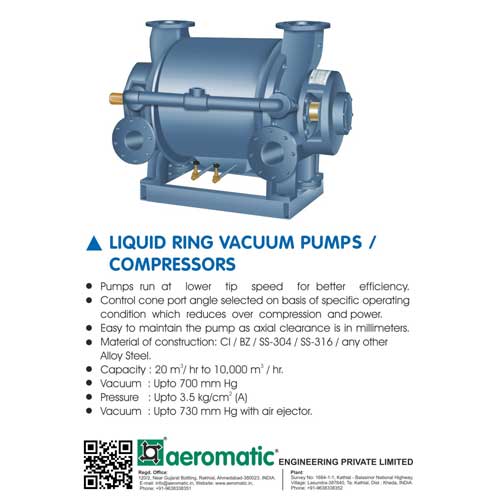
Liquid Ring Vacuum Pumps/Compressors
Compressors and Allied Equipment
Aeromatic Engineering Private Limited offers a wide range of liquid ring vacuum pumps/compressors.
Read more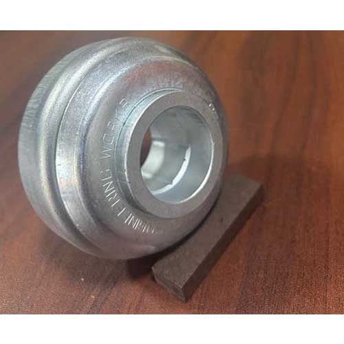
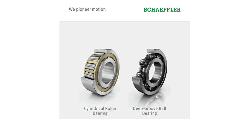
Hot Wheel Bearing
Bearings, Bushings, Wheels and Gears
SICCO Engineering Works offers a wide range of hot wheel bearing. Read more
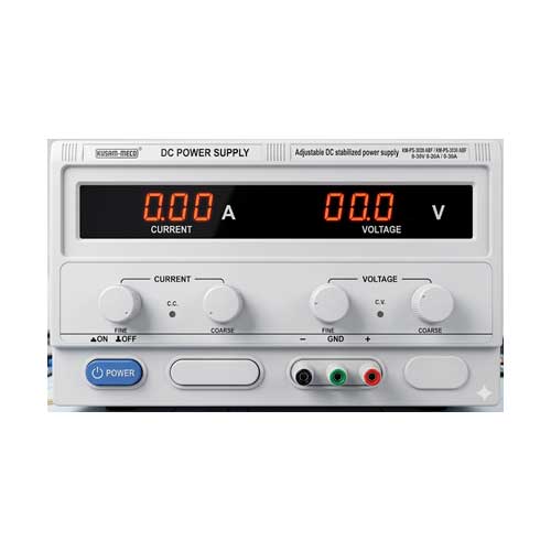
Kusam-meco DC Power Supply Model Km-ps-3020 Abf / Km-ps-3030 Abf
Power Supplies, Batteries & Accessories
<p>Kusam Electrical Industries Ltd offers Kusam-Meco DC power supply model KM-PS-3020 ABF/ KM-PS-3030 ABF</p> Read more
latest News
Subscribe to iNoW
For Industry News on WhatsApp, Give a Miss Call on: +91 84228 74016