


Schedule a Call Back


CYCLOCUT Advanced Cutting, Skiving and Semi-Completing of Bevel Gears in Low Quantities
 Technical Articles
- Jan 03,12
NULL

 Low quantity bevel gear sets can be manufactured with the Cyclo-Palloid? method. Cyclo-Palloid uses interlocking face hobbing cutters with 5 starts in most cases. For the soft cutting each cutter start includes separate outside and inside roughing and finishing blades. Figure 1 shows an interlocking Cyclo-Palloid cutter head where the centre part carries an inside roughing blade and an outside finishing blade. The interlocking second part of the cutter carries the outside blades. The cutter as shown in Figure 1 is set up for the soft cutting operation. The same cutter head can be used for hard finishing by skiving. The finishing blades are replaced by skiving blades, which commonly have brazed on CBN (Cubical Boron Nitride) inserts on the cutting edges. The roughing blade slots are not used during the skiving operation.
Cyclo-Palloid is a continuous indexing face hobbing method with parallel depth teeth which is based on conjugacy. This means without any flank corrections the pinion and gear flanks would contact along contact lines in every roll position. While rolling through an entire tooth mesh, the transmission ratio in case of conjugacy is perfectly constant and equal to the ratio of the pinion and gear tooth count. The motivation to use two part interlocking cutters is based on the idea of applying a mathematically simple method to generate length crowning by combining nominal inside blade diameters with outside blade diameters which are larger than nominal. The enlarged outside blade radii generate outside flanks, which will, in interaction with the nominal inside outside flanks, lead to length crowning controlled by the amount of outside blade point diameter increase.
 The graphic in Figure 2 shows how the two different pitch point diameters are arranged to be approximately tangential in the center roll position at the tooth mid-face. In order to accomplish the correct position of the two interlocking cutter parts, a main (outer) spindle carries the outer cutter part, while the inner cutter part is connected to a secondary (inner) spindle. The secondary spindle is positioned at an eccentric position relative to the main spindle, such that the two pitch point circles contact each other at the calculation point in mid-face position and the offset lines of both cutter parts lie on top of each other and are perpendicular to the flank line tangent (see Figure 2).
Profile crowning in Cyclo-Palloid is generated with curved blade cutting edges. Both pinion and gear are strictly generated bevel gears, there is no non-generated version of Cyclo-Palloid available[1]. A hypoid offset of the pinion versus the gear is basically possible but very seldom used in practical applications.
Introduction of Cyclocut
Related Products

Heat Exchanger Scale Removal Compound -hesr-300
INDUSTRIAL AUTOMATION & TECHNOLOGY CONSULTANCY
Read more
Request a Quote


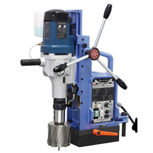
Universal Tapping Machine -model Tr-10/15
MACHINE TOOLS, POWER & HAND TOOLS
Tapping
Machine Tools offers universal tapping machine -model TR-10/15.
latest News
Subscribe to iNoW
For Industry News on WhatsApp, Give a Miss Call on: +91 84228 74016

Log In
To Contact this Supplier
Please Log In to your Account
INDUSTRIAL PRODUCTS FINDER (IPF) is India’s only industrial product portal. Referred to as the ‘Bible’ of the manufacturing sector in India,
Hi There!
Now get regular updates from IPF Magazine on WhatsApp!
Click on link below, message us with a simple hi, and SAVE our number
You will have subscribed to our Industrial News on Whatsapp! Enjoy