Schedule a Call Back
Top 10 tips for durable energy supply system on 6-axis robots
 Industry News
- Nov 01,22
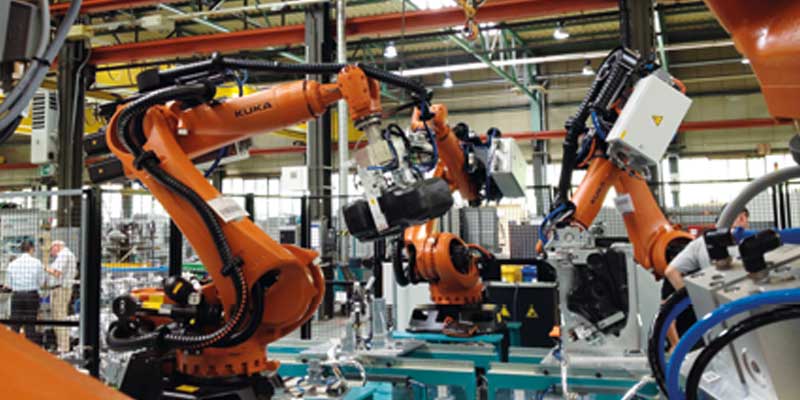
Six-axis robots are often used in automated production lines, which the system integrator sets up and commissions on site on a turnkey basis. Increasingly, however, medium-sized companies are using these robots in stand-alone applications and they are asking themselves the question: How should the energy, signal and if necessary, pneumatic supply, be implemented on the robot arm?
This article answers that question with ten tips. In the first part (Tip 1 and 2), it gives guidelines on the selection and configuration of multi-axis energy chains. A key aspect of this is the question: is a retraction system needed, and if so, which one?
The second part (Tip 3 to 6) describes the necessary work steps for installing the energy chain on the robot. In the third and last part (Tip 7 to 10), recommendations are given for testing and commissioning the installed energy chain.
The article is intended to facilitate the work of those designers, project planners and users who do not configure multi-axis energy chains and prepare robots for integration into production on a daily basis. However, it can only provide general information. For further, individual support in the selection, configuration and assembly of multi-axis energy chains, igus offers comprehensive assistance:
Bend radius: Bend radius is the radius with which the triflex R energy chain can be bent to the minimum without damaging it
chainflex: Brand name of the igus product range of highly flexible, torsion-resistant cables, also with special cables for robot applications (CFROBOT)
Fibre rod: Simplest version of a retraction system; allows partial directional control and stiffening of a multi-axis energy chain (see Tip 2)
readychain: Harnessed, ready-to-install energy chain systems (dress-pack) for immediate installation on the robot or in addition with a retraction system that is installed in combination on the robot
Retraction system: Ensures safe cable guidance on the robot arm and prevents looping and collisions of the energy chain with system components (see Tip 2)
Torsion stop: Design element for each chain link of the triflex R energy chains, ensures an even distribution of the torsional load over the complete cable length
Ball and socket principle: In the multi-axis moving energy chains, the chain links are connected to each other according to this principle, which is what makes the 3D movement and torsion possible in the first place
Shortening and lengthening: Each triflex R energy chain can be individually adapted to the application by inserting or removing chain links
Tip 1: Selection and configuration of the energy chain
The project planning starts with the definition of the required cables and hoses as well as their outer diameter and number. This results in the size of the energy chain from the igus triflex R product range. The bend radius of the energy chain and cables should also be taken into account in the selection.
In addition, the energy chain and retraction system size should always be in relation to the robot size. On the one hand, with small triflex R energy chains (size index 30 - 50), there is a risk that they will get caught more easily between the joints or get stuck on larger interfering edges. On the other hand, the retraction force of a small system is no longer sufficient to retract the energy chain sufficiently due to the filling and the possible arm length of a large robot.
Rough rule of thumb: From 90 kg payload of the robot, choose a 60 size or larger.
Note: To define the optimum chain size for the required cables, igus offers the ideal tool with the online interior separation configurator. Here the cable package can be virtually tested in every chain size and with every chain type. In this way, the optimum chain size can be determined without risk and subsequent lack of space for the cables.
In robotics applications, cables are subjected to high stresses due to the multi-axis movement. Here it is essential to select cables that have been developed from the ground up for moving applications. With the chainflex product range, igus offers a selection of 11 cable types that have been explicitly designed for use on robots (CFROBOT).
To answer the question of whether the energy chain should be open or closed, the ambient conditions are critical. If the robot carries out mechanical processing, for example, and metal chips are to be expected in the work area - according to the recommendation of igus a closed energy chain should be used.
Based on this pre-selection, the user can create a drawing of the interior separation with the igus interior separation configurator. This user-friendly online tool ensures an even distribution of the cables in the energy chain. This results in a safe cable guidance, which leads to a long service life of the energy and signal supply system to the tool or gripper of the robot.
Note: Take advantage of the flexibility of the energy chain. Select the size of the triflex R so that you can insert one or two additional cables later if, for example, an additional sensor is to be installed on the tool.
Tip 2: Selection of the retraction system
Retraction systems are available for the three energy chain types TRE, TRC and TRCF, which ensure a controlled movement of the energy chain. There are different systems to choose from. The environmental conditions as well as the available installation space ultimately determine which one is used.
Simple movements: In many applications e.g. palletising, the 6 axis robot performs only simple, barely superimposed movements. The cables only have to be held and guided above the robot arm. The fibre rod is ideal for this task: a simple component that provides directional control of the energy chain.
Confined spaces: If space is limited in the robot cell and the energy supply must run close to the robot arm and perform a certain length compensation, the RS system is the ideal solution. With its internal spring rods, it ensures directional preload and always returns to its initial position. Loop formation on the robot arm is reliably avoided. This system is also particularly suitable for applications with high levels of contamination.
High retraction forces, long robot arm: Similar in design to the RS system, the RSP retraction system differs in the continuously adjustable retraction force generated by a pneumatic cylinder. The ideal application for this system: When the hose package or dress-pack has a large number of cables and hoses and therefore a high retraction force is required. Another area of application is robots with a very long arm, which requires a long moving end chain.
Linear and compact cable guide: Due to its narrow and straight shape, the RSE linear system is space-saving. In addition, the linear shape makes it suitable for guiding laser welding packages or supply hoses for rivets, screws or bolts. The straight guidance of the cables and hoses ensures less wear with a retraction distance of up to 490 mm.
Lightweight and highly dynamic: When robots with low to medium load capacity are used in dynamic applications, the compact and lightweight RSE system with guide roller for energy chain sizes 40 to 50 is often the best choice.
Space-saving and cost-efficient: The RSEL (Retraction System Expander Linear) and RSSL (Retraction System Spring Linear) are space-saving due to their straight shape and even more price-efficient compared to the RSE linear. With them, retraction paths of up to 380 mm can be achieved.
Space and weight saving: The TRX energy chain completely dispenses with a retraction system, as the energy chain can lengthen by up to 40% due to internal elastomer bands and can also retract itself. This energy chain form combines all the advantages of the TRC and TRE with the characteristics of a retraction system. Only one standard mounting bracket is required to install the TRX energy chain. This saves weight and reduces the number of mounting parts on the robot.
Whichever system is chosen, the appropriate joining links from the robot to the retraction system must now be selected.
Tip 3: Order
Now the selected energy chain system or the one determined in the configurator can be ordered - including the feed-throughs and mounting brackets.
Before placing the order, it is worth taking a look at the diverse igus range of accessories. With components such as covers (for additional protection against external influences), adjustment units, adapter brackets, etc., the energy chain can be adapted even better to the individual operating conditions of the robot.
At this point, the user must also make a decision:
Tip: In order not to forget any attachments and to define the system that fits your robot, the online configurator for robot equipment is the easiest and fastest way to have the complete system.
Tip 4: Installing the attachment parts
If the user has decided to carry out the assembly themselves, they first install the joining links that were ordered and supplied on the robot. In the case of the fibre rod module, this includes the universal assembly kit, which can be installed on almost all robots thanks to the slotted holes. When installing retraction systems, it may be necessary to use an adapter.
Tip 5: Filling the energy chain
The next tip (for self-assembly) is to fill the energy chain with hoses and cables and - if not done before - to harness the cables. For the TRC energy chain, the cables should always be inserted first before they are harnessed.
When filling, the cables and hoses should be distributed as evenly as possible but not necessarily spatially separated from each other. Due to the chambers of the energy chain, a spatial separation is easily possible and is a common practice. The heaviest cables or hoses should not be arranged next to each other, but opposite each other.
Note: In order not to complicate the installation of the connectors, the cables and hoses should have sufficient excess length on both sides compared to the energy chain. In addition, it should be considered after installing the connectors if it is difficult or impossible to pull the cables through the energy chain due to lack of space.
Tip 6: Connection of the dress-pack to the retraction system
Now the filled energy chain is connected to the retraction system.
The user can skip this step if they order the energy chain generated in the configurator as readychain. Then the ready-to-install energy chain is delivered to him with igus function guarantee and approximately adapted strain relief.
Tip 7: Strain relief of cables and hoses
Generally, strain relief on one end is recommended. The reason for this is that the movement allows a length compensation to take place across the cables. In this case, the strain relief prevents the cables from being compressed or overstretched, which has a positive effect on the service life of the cables.
The console robots are an exception. Due to their movement sequence ("bent" from top to bottom), strain relief on both ends is recommended here so that the filling cannot move in the direction of the 6th axis.
Light fillings are to be fixed on the moving end side (axis 6) by a mounting bracket with strain relief teeth and cable tie wraps. For heavy filling, for example, with coolant or hydraulic hoses, CFX U-clamps are recommended in conjunction with a C-rail and a heavy-duty connection.
Tip 8: Test run in manual mode
Now, the robot, retraction system and energy chain are mechanically and electrically connected, and the robot is functional.
As a first tip for commissioning, all programmes should be tested in manual mode. In doing so, it is important not to forget the service or maintenance position. The functions in special operating modes (set-up mode, etc) should also be checked.
Tip 9: Test run in automatic mode
(Place 2 Images with "X" mark from “Page 14” of PDF here)
If the test run in manual mode goes smoothly, the test in automatic mode follows - initially at low speed, the jogging is increased up to production speed.
It is essential that the user has a free view of the dress-pack or the energy chain and also keeps an eye on it, because the energy chain or the dress-pack can behave completely differently at higher speeds.
Tip 10: Fine adjustment and checking
Now the robot together with energy chain(s), cable and dress-pack as well as, if necessary, the strain relief is "tried and tested" and ready for use. As a final tip before starting in normal operation, visually inspect the system and do a fine adjustment. This includes checking all strain relief elements as well as the screws and other joining links.
For more details, contact Matthias Meyer (Email: mmeyer@igus.net) or Markus Hörter (Email: mhoerter@igus.net)
Related Stories

More safety in cleanrooms with igus’ new polymer ball bearings
The company is adding abrasion-resistant xiros ball bearings to its portfolio for semiconductor manufacturing and battery production
Read more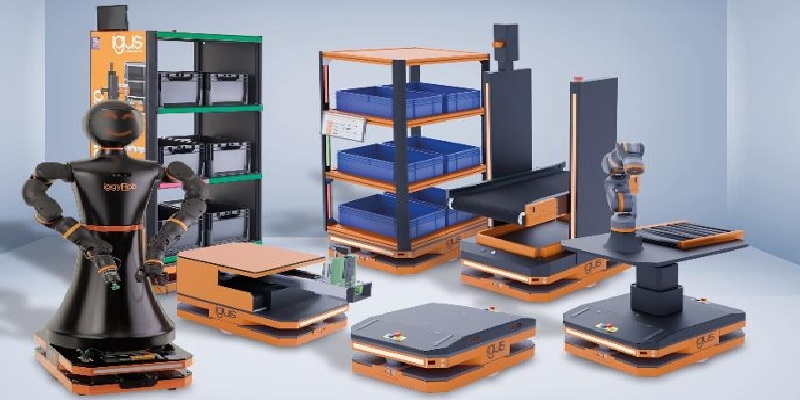
ReBeLMove Pro: Modular robot platform for logistics, assembly and handling
It is based on a compact, rectangular transport robot on four wheels with an electric drive.
Read more
igus Unveils Low-Profile Cable Guide System: No Chain, More Efficiency
igus introduces a new low-profile cable guide system, eliminating the need for traditional energy chains. Ideal for space-constrained and cost-sensitive applications, it ensures safe, efficient cabl..
Read moreRelated Products
Digimatic Smart Caliper
Veekay Industries offers a wide range of digimatic smart caliper.
Compact Fmc - Motorum 3048tg With Fs2512
Meiban Engineering Technologies Pvt Ltd offers a wide range of Compact FMC - Motorum 3048TG with FS2512.
Digital Colony Counter
Rising Sun Enterprises supplies digital colony counter.


