


Schedule a Call Back


Tips to manufacture pressure vessel using metal 3D printing technology
 Articles
- Oct 18,24
Arc-based metal 3D printing can be more flexible and economical than machining or forming processes, especially in case of complex geometries. There are compelling reasons to use them to additively manufacture pressure vessel.
Arc-based metal 3D printing is well on the way to radically changing metal component manufacturing. The near-net-shape additive manufacturing process with welding wire shapes three-dimensional objects by applying welding beads layer by layer. Examples can be found in the fields of plant engineering, aircraft construction, and toolmaking or lightweight construction. This is particularly advantageous for complex geometries with a high proportion of machining. Here the process is more flexible and often more economical than machining or forming processes. There are also benefits in the spare parts business, prototype construction, and small series production. Standards for metal 3D printing are now available in North America, and are in progress for additively manufactured, unfired pressure vessels in Europe. Linde Engineering, MIGAL.CO, TÜV SÜD Industrie Service GmbH, and Fronius International GmbH are taking the lead with the intention of helping the wire-based manufacturing method make its final breakthrough.
Tailor-made and just-in-time components
Classic manufacturing techniques such as casting are often associated with the construction of complex moulds and tools. There are also lead times and development costs to consider. Companies that adopt metal 3D printing can significantly shorten their production cycles. Additive manufacturing processes not only drive the rapid production of sample parts (rapid prototyping), but also just-in-time manufacturing. As such, they help to avoid risky single source situations—in other words, dependence on individual suppliers, and the associated high storage costs. When various components are needed, the correct “recipes” are selected in the software and “printed” as required. There are hardly any limits for component geometries. By contrast, topology and flow-optimised designs feature prominently in everyday production in additive manufacturing—even for large components.

CMT welding process ideal for metal 3D printing
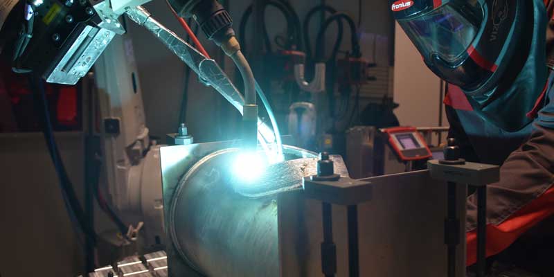
3D printing works with various processes. Wire-based processes such as “Fronius Additive” melt the welding wire, building up the workpiece layer by layer. To stop too much heat flowing into the workpiece, they must be designed to apply as little energy as possible. The MIG-based Cold Metal Transfer welding process (CMT) from Fronius is especially suitable for metal 3D printing of aluminum components. CMT is a “cool” dip transfer arc process that minimizes the heat input, despite its high deposition rate. This process is therefore ideal for additive welding, where the cyclical build-up of beads causes a high heat input.
CMT supports functions that are perfect for metal 3D printing. “Power correction” is a typical example. This function allows the electrical power to be precisely adjusted to the respective process phase while the deposition rate remains constant.
“With our CMT Additive Pro functions, specifically developed for additive manufacturing, such as power correction, or the Deposition Stabilizer that keeps the deposition rate constant, we can precisely control the power input and thus the height and width of the weld,” explained Leonhard Reiter from Fronius R&D.
Developing standards for additively manufactured pressure equipment
As a member of the “Joint working group for additively manufactured components under the Pressure Equipment Directive of the German Institute for Standardization (DIN),” Fronius participated in the model qualification of an additively manufactured component in collaboration with MIGAL.CO, Linde Engineering, and TÜV SÜD. The working group assessed the applicability of the draft standard prEN 13445-14 to the components of unfired pressure vessels.

Drawing on their particular areas of expertise, the participating partners carried out material qualification, design review, process qualification, additive manufacturing, component and pressure testing, as well as full documentation of the process chain, at their respective locations, and a binding additive manufacturing procedure specification (AMPS) was subsequently created.
“The entire value chain, including all the monitoring details, is considered in the draft standard for prEN 13445-14, and in the previously published DIN/TS 17026. This ensures that the fundamental safety requirements defined in Pressure Equipment Directive 2014/68/EU can be met,” said Dr Kati Schatz, Linde Engineering, outlining what is in the forthcoming standard. “All the details are included. This applies in particular to the material requirements, design, qualification of the additive process, manufacturing and testing, as well as acceptance and documentation. There is hardly any difference between this procedure and that for conventionally manufactured pressure vessels. Even though it has yet to provide the “presumption of conformity” of the intended harmonized standard, and there will still be revisions, the specification can nevertheless serve as a guide for all those involved in the additive manufacturing process of pressure equipment.”
Design, material, and filler material
The entire process chain was checked using a pressure vessel in the form of a pipe branch. As per the design template, the branch (additively applied area up to the stub) was formed on a conventionally manufactured base pipe with a cut-out provided for this purpose. This is known as a hybrid component, because the substrate material to be welded on will become an integral part of the pressure vessel.
“We decided to use aluminum as the material. We use the naturally-hardened wrought alloy in plant construction because of its excellent low-temperature toughness down to minus 273°C. Welding the material is challenging, however. It’s not just the choice of process and the process parameters that are crucial to the result, but also the choice of filler material,” explained Martin Lohr, Linde Engineering.
The filler material plays a key role in metal 3D printing, as tight tolerances apply both to the diameter and to the chemical composition, with the aim being to include as little hydrogen as possible. Furthermore, the wire must be free of inclusions and neatly wound onto a spool to ensure that the manufacturing process runs smoothly.
“The carbon footprint of the welding wire is an important environmental aspect, because it’s relevant in terms of the climate impact,” pointed out engineer Robert Lahnsteiner, CEO of MIGAL.CO, adding: “Ours is 3.8 kg CO2 per kilogram of aluminum, which amounts to less than a quarter of the international average.”

Designing the component and selecting the process
The aim was to optimise the transition from the base pipe of the pressure vessel to the stub in terms of both flow and topology. The design resulted in the following wall thicknesses: 8 mm for the base pipe, 14 mm for the transition from base pipe to branch, and 5 mm for the branch.
Selecting the direct energy deposition process
The essential requirements for the DED (Direct Energy Deposition) process, also known as the wire arc additive manufacturing process, were as follows for the model qualification of the pressure vessel:
- The highest possible deposition rate
- A reduced-heat process to avoid or minimize the cooling requirement and distortion
- No lack of fusion in the connection to the base material
- Insensitive to changes in the distance between welding torch and component
- Absolute reproducibility of the high material quality required within the qualified limitations of the deposition process
- Suitability for large components
Based on the requirements, the MIG-based CMT process was chosen for the additive build-up of the weld layers—specifically, CMT mix for the first layers and CMT Additive Pro for the subsequent wall build-up, where the use of power correction significantly influenced the heat input.
Qualifying the process
Due to the different wall thicknesses of the transition from the base pipe to the branch, the scope of application of prEN 13445-14 required three separate process qualifications (DPQR). The resultant deposition procedure specifications (DPS) are binding for the additive welding process. The final “recipe” for metal 3D printing, the so-called additive manufacturing procedure specification (AMPS), thus comprises three deposition procedure specifications, instructions for the welding sequence, and notes on material certificates and operator qualifications.
“In addition to welding guidelines, material certificates and operator qualifications are what ensures a consistent standard of product quality for additively manufactured components,” explained Manfred Schörghuber of Fronius R&D.
The individual test pieces were subjected to non-destructive and destructive testing as per the requirements of prEN 13445-14. Visual and dimensional tests (VT), volume tests (RT-D), and surface tests (PT) were used as non-destructive testing processes to provide evidence that the pieces were free from faults both externally and internally.
“We demonstrated that the mechanical and technological requirements for the additively manufactured material and the hybrid connection were met by checking the chemical composition and by conducting tensile and bending tests perpendicular to the direction of the deposition layer. We then performed metallographic analyses at the start and end points, and at the hybrid connection,” explained Martin Boche from TÜV SÜD.
Planning and simulating the robot path
The path for the robotic welding task was planned using a three-dimensionally modeled pipe branch in the CAM software (computer-aided manufacturing software) developed at Fronius.
“We calculated the proposed additive build-up—the actual welding program—by entering the layer height, position, speed, and build-up strategy. The welding path was visualized in a robotic welding cell that we modeled in our software,” added Leonhard Reiter of Fronius R&D.
Position sensing and sensor travel
The component was scanned using Fronius WireSense so that it could be perfectly positioned and corrective action taken with regard to the manufacturing tolerances. This innovative sensor technology uses the wire electrode as a tactile sensor and scans the welding contour point-by-point. If the electrode extension touches the surface, a short circuit occurs, which triggers a distance signal and transfers it to the welding robot. The system’s software compares the target value programmed offline with the actual value of the WireSense travel, and corrects the welding path for additive manufacturing as necessary. The wire then immediately moves backward and—while the robot continues moving the welding torch—forward again to the next point, where a further short circuit is triggered, a distance signal is generated, and the welding path is modified again, if necessary. This minimises geometric deviations.
Producing the component
The various wall thicknesses in the transition to the branch were implemented via different oscillation amplitudes. A constant heat balance was required to ensure the necessary optimal weld toe from bead to bead, and the uniform weld seam flow. Layer-specific welding jobs with specific parameters were used for this.
A water supply and return were provided for the component during the welding process. The water level this produced had to be far enough away from the welding point to maintain the interpass temperature in the qualified area. This allowed continuous welding without cooling breaks. Cooling of the component minimized component distortion and increased the deposition rate.
“To observe the build-up of the layers, we used a camera that was triggered in synchronization with the process. This allowed us to analyse the process deviations more accurately afterwards,” added Reiter of Fronius R&D.
Monitoring parameters and documentation
The WeldCube welding data management software monitored the parameter limits stated in the AMPS (additive manufacturing procedure specification) and issued a warning as soon as the preset limits were exceeded. The sum of all the parameters yielded the “fingerprint” of the additive build-up and facilitated analyses in the event of possible discontinuities.
Final component testing and looking ahead
The final testing, including confirmation of CE conformity, was performed by notified body 0036 of TÜV SÜD Industrie Service GmbH. In the present case, a starting material with mechanical data in a future, harmonized European standard (“harmonized” design) and a component of design class DC1, the result was a component inspection scope in accordance with the Table 1.
Table 1: Results of the test
Type of test | Testing processes | Scope of testing |
Non-destructive testing | - Volume testing (RT or UT) - Surface testing (VT and PT) | Per component, 100% of the relevant areas of the design (or 20% if using a suitable grid to fully cover the area) |
Destructive testing | - Chemical analysis - Tensile test to determine strength and elongation - Bending test | 1x in the additively manufactured area 2x in the unfavorable direction, and also in the hybrid area 2x in the unfavourable direction, and also in the hybrid area |
Final testing | Water pressure test Bursting test (optional) | |
“In parallel with these tests, we developed metallographic analyses covering especially those areas where imperfections had been detected. Also affected were the transition areas between the classic material and the additive welding deposition, the hybrid area. The main purpose of the metallographic analyses was to verify the data collected from parameter monitoring and from mechanical, technical, and non-destructive testing. In this case, samples were taken to gain a clear idea of the extent to which the material and the applied manufacturing process were flawless,” explained Boche.
Now that the conformity assessment procedure has been completed according to Module G of the European Pressure Equipment Directive 2014/68/EU, in the form of a “model qualification” of an additively manufactured pressure vessel with subsequent CE label to confirm compliance with the requirements of this EU directive, the pressure vessel joint working group of the German Institute for Standardization (DIN), represented by Linde Engineering, TÜV-SÜD Industrie Service GmbH, MIGAL.CO and Fronius, is looking to increase the acceptance of additive manufacturing in general, and in plant and container construction in particular.
“In conclusion, we can definitely say that decades of experience with arc-based welding processes—combined with stable and innovative processes such as Fronius CMT Additive Pro—offer compelling reasons to increase the use of metal 3D printing in plant and container construction. This creates a competitive edge, especially in view of the associated advantages such as topology optimisation, just-in-time manufacturing, and supplier independence,” summed up Schörghuber.
Article Courtesy: Fronius International GmbH
Arc-based metal 3D printing
Arc-based welding
welding
Fronius
metal 3D printing
pressure vessel
plant engineering
Linde Engineering
MIGAL.CO
TÜV SÜD
machining
Related Stories
Electrical & Electronics

Philip Harting appointed to VDMA Main Board
Philip Harting joins the VDMA Main Board to represent mechanical and plant engineering amid industry transformation, geopolitical challenges and supply chain disruption.
Read moreMachine Tools & Accessories
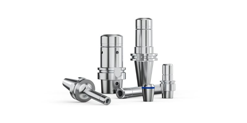
Seco Enhances ER HP Collet Chucks for High-Speed Milling
Seco has enhanced its ER HP Collet Chuck range for high-speed milling and 5-axis machining, offering smoother finishes, longer tool life and reliable clamping.
Read moreElectrical & Electronics
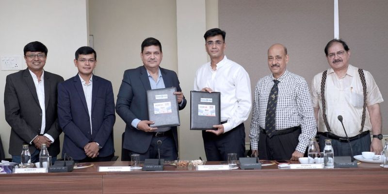
INOXCVA, ITMBU To Develop Semiconductor Skilling Centre
INOXCVA and ITMBU will develop a Centre of Excellence in Vadodara to train talent in orbital welding, process piping and UHP gas systems for semiconductor and electronics manufacturing.
Read moreRelated Products

Hardy - Chassis Mounted Weighing Card for Rockwell PLCs
WELDING, SOLDERING & CRIMPING SYSTEMS
Kore Mechatronics Private Limited offers a wide range of
hardy - chassis mounted weighing card for Rockwell PLCs.
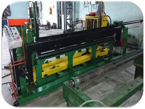
Tack Welding Machine
WELDING, SOLDERING & CRIMPING SYSTEMS
Invent Weld
Automation offers a wide series of tack welding machines.
Bench Welding Positioner
WELDING, SOLDERING & CRIMPING SYSTEMS
Toss Weldtronics
offers a wide range of bench welding positioners.
latest News
Subscribe to iNoW
For Industry News on WhatsApp, Give a Miss Call on: +91 84228 74016