








Schedule a Call Back


Relaybility - Selecting Industrial Grade Relays
 Technical Articles
- Feb 10,15
NULL

At first instance one may feel there is a spelling error in the topic of this paper, i.e., a mistake has happened in the word "reliability". But actually, a similar error may happen in the reliability of the Electrical or Electronic Control System if we do not give a second thought while selecting a Relay. After all a relay is a very simple product in which the coil changes the switch from one state to another when a rated voltage is applied to it. But the question is - is it really so Simple or we should give it a second thought...

Many RELAY users take a standard product for all applications and more often than not they're satisfied even if the relays are replaced frequently, much earlier than the actual electrical life cycle of the relay. This is due to the fact that not much time is spent on examining the important parameters necessary for optimum utilization of these switching interfaces. For sure, a same relay may work for all applications but not for the same period of time. It may be that as the application is different, so is the requirement of a relay. Otherwise, the relays wear out very fast or sometimes even create problems like contact welding and arcing.
Factors affecting performance of Relay
Many internal and external factors influence the performance of relay; they can be broadly classified into 10 key types: Each of these factors affects the relays performance in some or the other way. Based on the application one must carefully analyse all these parameters and select an appropriate relay as its failure is immediately reflected on the control system reliability.

1. Contact Material
The contact material has the major influence on the relay performance when it is compelled to be used under high current, continuous operation and connected load. The correct contact material is like the correct tyres for a racecar, as rally tyres are no good for a F1 car. The same is true for relays - the wrong material will have a big effect on its performance. For example a relay with AgSNO2 contact material may be good for inrush current but over a period of use its contact resistance increases drastically; whereas a relay with AgNi contact material is long lasting for control applications. There is no universal contact, which covers all applications. The selection depends on various factors like type of load, level of load, type of supply, frequency of switching, etc. Four different contact materials are widely used today for relays and their use is depending on their properties.

2. Coil Requirement
A user should give emphasis to the minimum pick-up voltage and the maximum permitted coil voltage with respect to the ambient temperature. In some circuit's leakage current or transient EMF might have enough voltage to keep some coils energised, therefore not releasing in the intended way. Different manufacturers specifies different coil voltage ranges, usually a 24 V DC relay has a working range of 0.80 to 1.1 times the nominal voltage UN.
3. Contact Requirement
As relays come in different configuration, thus several points of concern arise in choosing the number of contacts required for the application. The question remains "How many poles (contact sets) does the user requires for the application?" Relays typically come in 1, 2, 3 and 4 poles and less mainstream relays come with more than 4 poles. The contacts can be understood on the basis of terminology of NO = Normally Open, NC = Normally Closed, CO = Change Over contacts (change from one set of contact to another) respectively.
CO=Change Over contacts can further be described as SPST (Single Pole Single Throw), SPDT (Single Pole Double Throw), DPST (Double Pole Single Throw) and DPDT (Double Pole Double Throw). SPST being the simplest of all with only two contacts. SPDT has three contacts. The Double Pole versions are similar to Single Pole versions except there are two switches that open and close together. Special attention should be paid while selecting the contacts in accordance to the voltage and current requirements of the load.

4. Socket/Base
This is one of the most important and usually the mostly ignored parts of a relay used in a control system. The users must keep in mind that the relay can get only as good as its Base or Socket. The best of the relays will under-perform if the mating socket is not optimised with respect to the relay.
The important bit is quality of materials and plating's in the base, the plastics need to withstand the heat generated from the contacts both in the relay, and the contact made between the terminal and the relay base, and the metal needs to have enough elasticity force to maintain its pressure on the terminals, usually this is where improperly designed bases/sockets fail and let down the electrical system, the clamps in the base open up with heat and fails to return to its original position, and this reduce the pressure, and increasing heat, until a failure occurs.
The relay and the base/socket, in all cases, should be made by the same manufacturer as per the specific mating requirements and considerations.
The secret to a good electrical connection is the result of Area x Pressure. If a joint is made up with too little pressure, moisture and air will penetrate the joint and promote corrosion which raises resistance which increases heating which can accelerate corrosion.

5. Type of Load
It is important to determine the parameters of relay in accordance with the type of load connected. Loads can be of different types, e.g., Resistive, Inductive, Capacitive, Lamp Load, Motor Load, etc. Some loads like motor and inductive loads have high inrush current and can damage the contacts of relay if not selected properly. An additional protective circuit may be required to overcome the ill effects of the using inductive loads and to increase the service life of the relay and the system.
A basic separation should be maintained between large AC and DC Loads. When switching large AC loads, the relay can be operated up to the mentioned voltage and current levels as the arc produced during the switching goes out in the next zero phase of AC cycle. However while switching DC loads, due to non availability of Zero Crossing to extinguish the arc automatically, a standard relay can only switch relatively small DC load.
In industrial applications demanding switching high DC loads, a user has an option to connect two contacts in series to increase the switching capacity. (As shown in the graph below).

6. Insulation
The main functions of a relay is to connect and disconnect different electric circuits, and usually, to maintain a high level of electrical separation between different circuits. It is therefore necessary to consider the level of isolation in accordance with the EN 61810-1 standards appropriate to the application and the task to be performed and relate this to the relay's specification.
7. Temperature
Temperature plays an important role in defining the electrical service life of a relay. The relay exposed to harsh ambient temperatures would lead it to work unreliably. While designing the system it is therefore necessary to take temperature as the main criteria. A typical Coil Voltage variation graph with respect to temperature is shown below.

8. Type of Mounting
Today depending on the application type, a user has different options for mounting the relay; the most common being the PCB version. These types of relays can directly be soldered on a PCB. In industries however socket/base mounted relays are preferred because of their modularity and ability to mount on DIN rails or screw mounting on panels. Third type of mounting is flange mounting, which is used if there is no DIN rail available.

9. Life Time
For a reliable switching interface, a relay should typically have an electrical service life in few hundred thousands of switching cycles so as to efficiently work for a higher life span. This electrical life must be tested for a relay at the required ambient temperature which in Indian conditions are definitely above 40?C for air conditioned environment and 60?C for uncontrolled environment. For records, it is important to check whether the relay selected has been tested for electrical life at the ambient temperature specified by the relay manufacturer in their data-sheet.
The Service factors are considered when there is a need to diagnose a fault in the relay and also the ease with which they relay can be replaced in an existing control system. It is very important to have indication for both - the Coil Actuation as well as the Contact Latching, so that the user can identify the nature of the fault.
10. Service Factor
After the fault is diagnosed, the user needs an easy identification of the key technical parameters of the relay, so that the correct replacement can be ensured without looking at extensive documentation. For this purpose, it is important that the technical parameters are Laser printed on the relay, as the ink printing normally wipes out over a period of time.

Conclusion
The reliability of relay plays an important role in the availability of control system. For each application therefore the best relay shall be chosen based on different technical parameters. With the advancements in technology and the multiple options now available in these relays, the need of the hour is for optimisation of the selection parameters. This kind of design elevation if considered at the time of detailed engineering can help in:
- Increasing reliability of control system
- Reducing the cabinet footprint
- Removing the wiring errors
- Preventing additional heat generation inside the cabinet, and
- Saving space and optimising costs directly as well as indirectly by energy saving.
About the Author:
Dr Ashish Manchanda is the Managing Director of Finder India Pvt Ltd. He has been associated with Electrical, Instrumentation and Automation Technology since the last 22 years, which has provided practical and hands on experience in designing, maintaining and servicing of control system solutions as well as automation components for various segments of industry. He has travelled to different end users in the past many years to offer solutions on site. He is also a member of ISA Delhi Section, AIMA Delhi and Instrumentation Experts Club, Mumbai. Finder India Pvt Ltd, New Delhi. Tel: 011-47564343. Telefax: 91-11-47564344. Email: finder.in@findernet.commailto:finder.in@findernet.com
Related Products
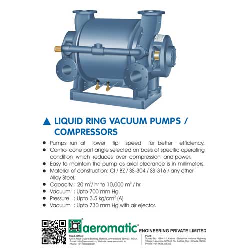
Liquid Ring Vacuum Pumps/Compressors
Compressors and Allied Equipment
Aeromatic Engineering Private Limited offers a wide range of liquid ring vacuum pumps/compressors.
Read more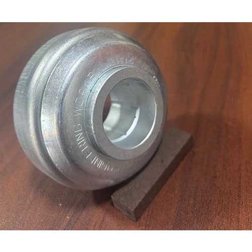
Hot Wheel Bearing
Bearings, Bushings, Wheels and Gears
SICCO Engineering Works offers a wide range of hot wheel bearing. Read more
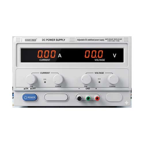
Kusam-meco DC Power Supply Model Km-ps-3020 Abf / Km-ps-3030 Abf
Power Supplies, Batteries & Accessories
<p>Kusam Electrical Industries Ltd offers Kusam-Meco DC power supply model KM-PS-3020 ABF/ KM-PS-3030 ABF</p> Read more
latest News
Subscribe to iNoW

For Industry News on WhatsApp, Give a Miss Call on: +91 84228 74016