Schedule a Call Back
Polygon Turning: Economical Alternative to Milling
 Technical Articles
- Nov 02,11
In the general component manufacturing industry, one can find processes for the primary operation like the cold forging, multi-spindle automats, and single-spindle automats. In recent times, CNC machine with bar is finding a predominant place. These primary processes are very well developed in terms of productivity, quality and the cost per piece. Not all parts can be completed by the primary operations and it warrants several secondary operations for the parts to be machined to the required specifications. When it comes to the secondary operations like the drilling, milling, slotting, broaching and the notching, well developed standard solutions are difficult to find. This is mainly because the secondary operations cannot be categorised and standardised. Each component needs a specific solution.
Trishul Machine Tools Pvt Ltd has made an effort to categorise these secondary operations and find an economical solution to machine these parts effectively. The secondary operations can be classified as:
- Drilling cross holes
- Slotting or making a key way, and
- Making external slots.
 These operations require specific solutions, as they cannot be rationalised. The following operations have been rationalised and the company has developed very economical machining solution for these operations:
- Machining hexagons
- Machining octagons
- Machining squares
- Machining flats
- Machining tapered flats
- Machining stepped flats/polygons
- Slots on the face
- Machining ratchet teeth, and
- Any other flat surfaces similar to the above.
Polygon turning is very different from other normal machining operations as this is a generation process. The tool and the job to be cut are rotating and the interference of them produces a flat surface. The locus of the point of contact of the two interposing circles, i.e., tool and the job is an "ellipse" of minor dia equal to the across flat size of the component and the major dia equal to twice the tool dia and the across flat size of the polygon. (See figure 1).
Generally, the ratio used is 2:1 but in special applications we use 3:1 and 2.5:1. The ratio 2:1 is the most preferred as this covers a vast spectrum of engineering applications. Trishul models TPT-1S and TPT-2S use this arrangement, which has a mechanical kinematics link. These are machines with parallel axis and suitable for producing Polygons along the axis of the component.
Trishul models TPT-4S and TPT-5S are more suitable for serrations, slots, profiles, such as ratchets and splines along the axis or normal to the axis. These machines have no kinematics link and the spindles are coupled by an 'Electronic Gearbox' and driven by servomotors. There is no limitation on the speed ratio of the spindles. Production of odd numbers and prime numbered serrations, which was other wise impossible, can be conveniently machined. The 'Electronic Gearbox' makes the spindle free of the driving elements and linkages; hence the spindle assembly is free to rotate to any angle. The freedom of the spindle to rotate to any angle opens new arena machining applications. Machining of starter pinion chamfer, pointing of synchro rings, ratchet teeth on the face and OD are the new possibilities on the polygon turning machine with 'electronic gearbox'. Odd numbers and prime numbers are a very common occurrence in these applications, which can easily be addressed.
The sides of the polygon generated by the polygon turning process are never flat but are very close to being flat as they are segments of an 'ellipse' near the minor diameter. The flatness of the sides of the polygon is dependent on various factors such as the Tool diameter, chordal length of the side of the polygon with respect to the across flat size, the length of overhang and the number of sides of the polygon.
The other significant factor affecting the flatness on the component is the dynamics of cutting. In general machining processes like turning and milling the dynamic geometry is very close to the designed geometry with a very slight change affected by the feed per tooth or feed per rev. The change becomes highly significant only when cutting threads of high helix angle. The dynamic geometry of tools in the Polygon Turning Process varies very significantly at every point in the locus of the tool path. It varies from one extreme to the other during the process of cutting. As a result of this the shear efficiency varies significantly from point to point on the surface being cut. In addition to the above the shear section i.e. the chip section varies from point to point in the process. (See fig ures 2,3,4).
 Unlike in turning where the disturbing forces are generally uniform through out the process, In polygon turning, the disturbing forces varies form point to point on the surface being machined owing to the varying dynamic geometry. The general practice is to cut polygons on the previously turned round parts. The chip section is a segment of circle hence it is not uniform. The varying chip thickness is another important factor contributing significantly to the disturbing force. Under these circumstances the stability of clamping and the natural stiffness of the part being machined have to be essentially rigid to resist the cutting forces, which are not uniform in nature The polygon turning process being intermittent cutting in nature, the tool is in contact with the job only for 20?~ 40? in its rotation of 360?. Before the chip can conduct the heat to the tool the, tool is out of engagement and the chip which carries the entire heat is thrown out of the tool surface. The tool travels the rest of the rotation in air, ready to take the next chip. This chip formation is a little different compared to the normal machining and the tool edge remains cool even after prolonged usage. This phenomenon enables us to use higher cutting speeds for the tools. Cutting speeds 35%~40% more than those recommended are very common. Machining of tough materials like SS316, SS302, Duplex stainless steel, Inconel, Monel, Hastelloy and Titanium alloys is made lot more hassle free by this phenomenon.
Trishul Machine Tools has standardised on tool holders of ?50 mm, ?80 mm, ?120 mm, ?140 mm and ?200 mm. We choose the diameter based on the size of the component, chordal length as a ratio of the A/f size, tolerance on the part and the permissible flatness error on the part machined. Large diameter tool holder produces a more flat surface, but at the cost of increased cycle time. At the same time lower the tool diameter faster will be cycle time at the cost of flatness. We have design models to predict the flatness error, and we optimise the tool diameter to strike a balance between the cycle time and the flatness error.
With the increase in the manufacture of automotive parts for domestic and international market, we see more and more demand for these machines in the future.
(Contact: C S ShivaShankaraiah, Managing Director, Trishul Machine Tools Pvt Ltd, Bangalore. Tel: 080-27836100, 27836166. Email: trishulmac@vsnl.com)
Related Products
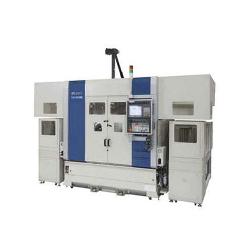
Compact Fmc - Motorum 3048tg With Fs2512
Meiban Engineering Technologies Pvt Ltd offers a wide range of Compact FMC - Motorum 3048TG with FS2512.
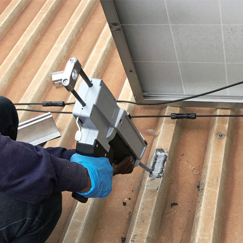
Structural Adhesive for Solar Panel Roof Mounting
Parson Adhesives India Private Ltd offers a wide range of structural adhesive for solar panel roof mounting – Partite 7535.

Industrial Tsn Switch
Contec launches a future-ready Industrial TSN Switch- SH-9210TSN.


