


Schedule a Call Back


Ideas on a New Stirrer Design
 Technical Articles
- Aug 11,10
NULL

 I have designed this stirrer with a very basic question in my mind, "Why do we need to use a stirrer in a reactor?" With the help of the following explanation I would like to answer this question.
The answer to this question is very obvious; for a common man the use of a stirrer is to enable agitation and mixing of two or more chemicals, ideally to produce a new product. But, the same task can be achieved just by keeping two or more chemicals in contact with one another; the chemicals will react to produce a new product even without the presence of a stirrer. However, this process might take a longer time than needed.
The key to a chemical process is to achieve high degree of efficiency in a process by adopting different measures. To make chemicals react faster we add a catalyst or we try to supply external energy in various forms. External energies in the form of heat, pressure, electricity and motion (kinetic energy using stirrer) are used as and when appropriate. The idea behind applying the external energy to the chemical process is to provide more energy to the chemical molecules so they can react better and faster. To draw a bottom line, certain chemical processes need additional kinetic energy for efficient reactions. These are the cases where a stirrer is used to provide the additional kinetic energy. The key to the stirrer design lies in how efficiently the stirrer distributes its kinetic energy to the chemical mass in reaction. Normally, the basic source of the kinetic energy is the electric motor. A motor produces rotational motion. This energy is transferred through belt and pulleys to the gearbox, from gearbox to the stirrer shaft, from shafts to the blades of the stirrer and eventually to the mass in reaction. In this process we lose the energy at several places.
 We lose energy when the belt slips on the pulleys. Gears of the gearbox need some energy to move. By reducing the RPM through gearbox or pulleys we are allowing the kinetic energy to fall down. If we provide a stuffing box or mechanical seal, etc., some energy loses will occur due to frictional losses at this end. Now at the output, whatever energy is available at the end of the gearbox gets transferred to the solid shaft of the stirrer. Normally in common design stirrers, Anchor type, Paddle type, Propeller type, etc., we design the stirrer to distribute kinetic energy at its shaft to its blade tips, which is then distributed to the stirring mass. The goal is to break the static inertia of the mass and distribute higher kinetic energy into mass. The design of the blade of the stirrer will now decide the path for the moving particles in horizontal and vertical directions. During stirring, as the particles move away from the tip of the blade, their kinetic energy falls. If the blade has to push heavy mass upwards, against the gravity of the earth, the kinetic energy of the mass will fall down drastically as it will need to work against the gravitational force.
So, through these types of common stirrer designs, what we notice is a loss of kinetic energy at various levels of the machinery. We see a drastic difference in the kinetic energy of the particles near to the motor shaft than that of the particles further away from the blade tips. With such designs, our aim of maintaining a uniform kinetic energy throughout the mass in reaction is defeated.
 Whereas, in the case of my stirrer design, the kinetic energy generated at the hollow shaft of the stirrer increases right at the place of the coupling between the stirrer shaft and the motor. The reason being the diameter of the shaft of the stirrer, which will always be more than the motor shaft diameter and the RPM of both the shafts, which will always be same.
All the particles of the stirring mass, in my stirrer design, move towards the centre of the shaft cum impeller and always attain maximum kinetic energy compared to that of the common stirrer designs. After the mass enters the central shaft, the mass is directed downwards, which in turn experiences gravitational acceleration. Hence, due to the motion of the mass (downwards in my stirrer design) and the added gravitational force on the mass, the mass attains a much higher kinetic energy level as compared to motor shaft and what is attained at the tip  of the shaft in the common stirrer designs. With my design, the mass is brought to the centre of the shaft and dissipated from the bottom of the shaft, the process continues and with every cycle the mass achieves higher kinetic energy levels with the cumulative effect. Thus, an accelerated kinetic energy level is achieved from a constant speed motor drive. The optimum efficiency of a stirrer is utilized through this unique design. As the mass in reaction achieves higher and higher kinetic energy, it imposes less and less load on the motor; thereby achieving the desired result with less horsepower. All three different types of stirring effects (particle movement patterns) as seen in Anchor, Paddle and Propeller type stirrers are seen in my design stirrer; all three types, at a time.
And this exactly is the bottom line that we want to achieve through the use of a stirrer, which is, maximum kinetic energy to the mass in reaction.
I hope this brief explanation of my design will fetch a keenly anticipated response. (Readers' feedback welcome. Contact: Rajen Bhatt, Meticulous Creations, Vapi, Gujarat. Mobile: 098251-21527. Telefax: 0260-2421527. Email: stirrers@gmail.com, meticulouscreations@msn.com
A design that completely eliminates all problems
- The centripetal type stirrer consumes very low power, a unique design
- Only a hollow shaft is required as a raw material, does not involve fabrication cost as no blades, and can go for mass production
- Central guide is not required on long shaft lengths because the shaft experiences push from outer mass, which gets stabilised in a short span of running; the inside and outside liquid mass acts as a guide
- This design drives the material towards the centreline of the shaft. This needs very much less power, because the actual displacement of the material is limited to the shaft diameter to the centreline only
- Need not be dynamically or statically balanced for good performance, because normally a hollow shaft is a pipe section having almost uniform OD and ID and thickness. The mass of the shaft material, is quite negligible, compared to the mass it is stirring
- This runs at motor RPM. The power is required just enough to rotate a hollow shaft and to impart actual kinetic energy required to be given to the molecule to achieve highest rate of reaction in the process. So as a result a lot of power saving is achieved
- The gearbox is completely eliminated. It is directly coupled to the motor
- Runs at maximum efficiency
- Very easy installation from a manhole only - no cost burden in the reactor due to the stirrer
- The design has no limitations on selection of material of construction. It can be a hollow shaft of any material suitable to the chemical used, so always economical
- The crystalline material if stirred with conventional stirrer, the stirrer blades will hit the crystals as many times the blade RPM. In centripetal stirrer there are no salient projections on the shaft that can hit the crystal. Even the entry of liquid is tangential, which offers no obstacle in the path of the liquid. So the crystalline structure is not damaged. Because of these phenomena the mass does not become sticky. This helps a grate way in solid liquid separation of such crystalline material. Not only time is saved in separation, but this also eliminates need of vacuum or pressure for better dehydration.
- Thus it is very much economical, saves a lot of power, and up to 85% cost on raw material input, up to 90% reduced production cost, flexibility in selection of the materials of construction, no maintenance problems, one piece construction, no installation problems, crystals remain intact. Mass production can be achieved, helpful in air pollution control as well as effluent treatment, so it is environment friendly. This is the only stirrer design that generates accelerated energy. This reduces power demand with time.
Related Products
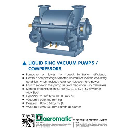
Liquid Ring Vacuum Pumps/Compressors
Compressors and Allied Equipment
Aeromatic Engineering Private Limited offers a wide range of liquid ring vacuum pumps/compressors.
Read more
Hot Wheel Bearing
Bearings, Bushings, Wheels and Gears
SICCO Engineering Works offers a wide range of hot wheel bearing. Read more
Kusam-meco DC Power Supply Model Km-ps-3020 Abf / Km-ps-3030 Abf
Power Supplies, Batteries & Accessories
<p>Kusam Electrical Industries Ltd offers Kusam-Meco DC power supply model KM-PS-3020 ABF/ KM-PS-3030 ABF</p> Read more
latest News
Subscribe to iNoW
For Industry News on WhatsApp, Give a Miss Call on: +91 84228 74016