Schedule a Call Back
Ethernet networks in railways
 Technical Articles
- Feb 01,16
– HEIKO FRESE
Ethernet’s standardisation as a control and communication network in trains is entering the final phase.
Train control systems must process different input signals and information in order to guarantee the safe transport of people and goods. So far in trains an MVB/WTB bus system has become established for this job and standards have been defined for the specific characteristics (components, interfaces and protocol). As in automation, where Ethernet has already become established as the network from the I/O level through the control level to the IT company network, Ethernet will also replace the MVB/WTB bus as the network infrastructure in trains.
There is a good reason for this technology’s assertiveness: Ethernet allows high availability of the hardware components, simple end user integration, and simple network scalability and expandability. The basic functions include setting up topologies for network redundancy and the possibility to prioritise data and to segment the physical network into logical networks. These options are the basis that makes Ethernet interesting for train control systems. There is also the trend toward standardisation. Unlike in automation, with its application-specific Ethernet protocols such as PROFInet, EthernetIP, EtherCat, Powerlink and Sercos, just one standardised approach is being pursued for train networks. It must be possible to configure the train system both as a composite of modular, freely coupled units and also as a composite of coupled train parts from different manufacturers over the network, and these parts must work together smoothly.
Within the IEC standardisation group, the requirements for topology, component interfaces and protocols were worked out and written down in the 61375 series of standards (final in 2015).
*IEC 61375-3-4 - ECN Ethernet Consist Network
*IEC 61375-2-5 - Ethernet Train Backbone
*IEC 61375-2-3 - Communication Profile
Train and car switches have been defined as the hardware. The networked train switches form the Ethernet backbone which is run in parallel through the train in order to increase the availability. The train switches are additionally redundantly connected to the higher level Consist Network.
Car switches in a ring topology in this “Consist” (= train unit) or “car” network, are defined in standards for connecting end users.
Error-resistant passenger information systems
While the final standardisation for Ethernet as a network for train control systems is still ahead, practically all current passenger information systems have already been implemented in an Ethernet network. Ethernet provides a uniform interface for display, camera, video recording and controller. Powerful IP cameras eliminate the need to convert analogue camera information for recording.
The selection of network topology and components is done independently of the application and is strongly stipulated by the train owners’ performance requirements. The systems are implemented as a line topology with “Plug&Play unmanaged switches” or in a ring topology and consequently as a redundant network with “managed switches”. For example, at HARTING, the Ha-VIS 4000 switch family offers robust and reliable solutions with an M12 interface for both topologies.
Due to the further progress of the integration of service functions with the simultaneous increase in the number of network users, Ethernet networks in trains must be planned for higher bandwidths.
Depending on the topology (line or ring), managed and non-managed Ethernet switches with gigabit interfaces are used. All Ethernet ports are executed with the vibration-tested M12 interface (D-coded for 100 Mbps and X-coded for 1000 Mbps). In addition to the improved performance for the data throughput (gigabit backbone), redundancy functions allow greater availability. Particularly for simple, planned (not managed) networks in a line topology, it only takes a power failure in one car to disrupt the information flow for the passengers. Switch models with a bypass function from HARTING ensure considerably better availability in comparison. For example, if there is a disruption in the power to one switch in the middle section of the train, the Gigabit Ethernet ports will be connected directly through and the Gigabit Backbone, which is the communication from the first to last train section, is maintained.
Switch models with “Power over Ethernet” (POE) are provided for the installation of camera systems to increase passenger safety. In this case the switch feeds the power supply to the PoE camera in a cable together with the Ethernet communication, which reduces the installation effort and the fire load (1 cable instead of the previous 2) in the train.
Passive network infrastructure
The required high availability of Ethernet networks in trains can be achieved only with the coordinated interaction of active (switches) and passive (connectors and cables) network infrastructure units. In trains, the M12 connector offers greater reserves for signal integrity and superior vibration resistance compared to the RJ45 connector. In addition to the proven M12 screw-on connectors, HARTING now also offers the innovative M12 PushPull termination technology that optimizes the handling and time expenditure for switch installation. When plugged in, the M12 PushPull sets up a reliable and shake-proof connection to the switch that snaps into place with an audible signal. Users can disconnect the M12 PushPull connector simply by pulling on the retaining ring. But a network in a train needs more than just reliable components such as switches and connectors especially developed for the point of use. The network cable, for example, the Ha-VIS EtherRail product family must also be designed for reliable and durable data transfer under the difficult ambient conditions. In addition to the design configuration for the best installation and transfer characteristics, all insulation materials are selected in accordance with the latest fire regulations and tested for use in trains. These network cables consequently actively contribute to optimising the fire load.
Managed switches optimise the network
Unmanaged topologies can be designed for perfect operation in terms of higher availability and data throughput by means of By-Pass and Gigabit Backbone.
For passenger information systems with more functions and users, however, the network optimisation gained by using managed switches should also be reviewed. Particularly the data traffic that ensures high data throughput by means of networking IP cameras and terminals/displays can be reduced by functions of managed switches.
Useful functions of managed switches
IGMP – Internet Group Management Protocol
Because video data require a significantly higher bandwidth than other data types, the IGMP protocol should be used. This protocol, together with the functionality of the switches that are used (snooping) ensures that the video data streams are transferred only to receivers who require them or have requested them. This keeps the data capacity utilisation as low as possible.
Redundancy provided by ring structures
By using redundant topologies – in the train, primarily planned as a ring structure – the loss of a connection can be overcome without a communication breakdown with managed switches, in interaction with the standardised protocols RSTP or MRP (Media Redundancy Protocol). These protocols deactivate redundant paths in a network that are then reactivated in the event of a problem (failure of a connection) in order to restore the data communication for all network users.
Virtual Local Area Network (VLAN)

Segmentation of networks in logical network group help increase network security. The various VLANs send and receive data only to or from devices that are members of this special VLAN. It is consequently possible to reliably delimit passenger services (Internet access) and train information data or services in the same physical network.
Link aggregation
Link aggregation or trunking is a switch feature that allows several physical network connections to be combined and administered in one logical connection. With Link Aggregation the bandwidth between the switches can be increased in order to deal with high network loads at special points. The availability is also increased thanks to the physical redundancy.
The author is Product Manager, Industrial Communication and Power Networks (ICPN), HARTING
Related Stories

PCIM Asia New Delhi Conference Debuts, Showcases Power Electronics Future
The inaugural PCIM Asia New Delhi Conference brought global experts, policymakers and industry leaders together to discuss high-efficiency power electronics and India’s evolving energy ecosystem.
Read more
TARIL Reports 32% YoY Revenue Growth, Q3 PAT Rises 37%
Transformers & Rectifiers (India) Limited posts strong Q3 FY26 results, driven by higher revenues, improved margins, healthy order inflows and leadership continuity.
Read more
Toyota Kirloskar Motor Showcases Flex-fuel Hybrid Tech
Toyota Kirloskar Motor highlights flex-fuel strong hybrid technology, skilling initiatives and industry collaboration at the Advantage Maharashtra Expo 2026 in Chhatrapati Sambhajinagar.
Read moreRelated Products
Compact Fmc - Motorum 3048tg With Fs2512
Meiban Engineering Technologies Pvt Ltd offers a wide range of Compact FMC - Motorum 3048TG with FS2512.
Structural Adhesive for Solar Panel Roof Mounting
Parson Adhesives India Private Ltd offers a wide range of structural adhesive for solar panel roof mounting – Partite 7535.
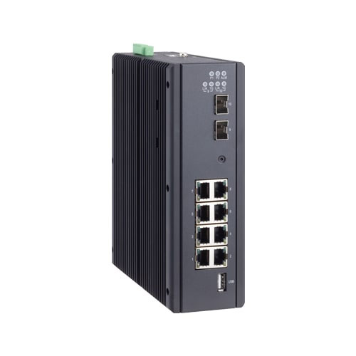
Industrial Tsn Switch
Contec launches a future-ready Industrial TSN Switch- SH-9210TSN.


