Schedule a Call Back
Manufacturing Aircraft Engine Components Using ECM/PECM
 Technical Articles
- May 05,14
According to the latest survey by Boeing, the number of aircraft deployed worldwide will double within the next 20 years. This will, of course, lead to an enormous increase in the number of aircraft engines required. But it is not only the increasing demand for engines that will pose new challenges to engine manufacturers, there are also ever tightening environmental standards to be taken into consideration.

The demands made on future aircraft engines are characterised by three prime criteria. Owing to ever greater cost pressures and fierce competition, the market calls for engines with noticeably lower fuel consumption levels. Environmental regulations are also getting tougher in their demands for a reduction in emissions. And there is a need to reduce purchase and maintenance costs of the new aircraft engines.
The two criteria of fuel consumption and emission levels are closely connected and are, to a large extent, determined by the design of the various compression stages of the engine. Every increase in efficiency brings with it a reduction in fuel consumption and, in turn, in CO2 emissions.

An increase in speed leads to an increase in the compression ratio between the various compression stages and to the desired increase of thermal efficiency. This strategy will, at the same time, bring about a reduction in the number of blades required, which - in turn - allows for an optimally aerodynamic design of the individual blade.
Higher speeds and higher temperatures exert ever increasing pressure on the compressor rotor - a fact that has to be taken into consideration by opting for an integral design. In other words, the interface between blade root and disk disappears and the rotor is produced as an integral component (blisk = blade integrated disk).

This ensures that the high loads on the blade root are absorbed, an elaborate interface is eliminated and the integral design provides for a mass-reducing construction that offers greater economic viability.
In the past, the choice of material used in such cases fell on nickel-based alloys, especially as the high operating temperatures in the high-pressure compressor environment had to be taken into account. To satisfy the still increasing demands for higher temperatures and a reduction in component weight the effort has, for some time, concentrated on the use of titanium alloys to replace them. Development in this area has meanwhile reached levels that cover the official approval of the material as safety class 1 in the sector "rotating components."
Compared to nickel-alloys the new material is even more difficult to machine, so that is imperative to find, for both materials, alternative production processes that satisfy economic and technological requirements. Against this background, it seems to be imperative to quickly introduce new production processes for the production of those aircraft engines still at the development stage, especially when one considers the overall requirement in blisk components over the next few years.

ECM Process
ECM (Electro-Chemical Machining) stands for the removal of metal through electrolysis, the workpiece being polarised positive (anode) and the tool negative (cathode). The working gap is flushed with conductive, watery electrolytes.
The application of a voltage leads to the molecular dissolution of the workpiece material. The material removed (metal hydroxide) is flushed out and separated from the electrolyte by a filtering system, making the electrolyte ready to be reused.
The ECM process has become known through its wide application as a deburring tool, especially in injection technology, where special design tools were used to remove material only at strictly localised points - to get rid of burrs or for the creation of radii. They were also used to create annular grooves, cavities and other structures.
Using 2.5D imaging technology and DC generators it also allowed for the implementation of countersinking processes. However, either the quality of the image proved mediocre or the development costs for the tools to achieve the desired geometry were too high. However, where the results fulfil the requirement, reproducibility of the process is good, tool wear is minimal and the hardness of the material has no negative influence on feed rates. If the machining surface for the cathode is increased, the process does not lengthen the cycle time.

PECM Process
With the subsequent development of the ECM process into PECM (Precise Electro-Chemical Machining) it became possible to increase the accuracy of the images and to reduce the development costs involved in the effort to arrive at the required final geometry.
To achieve a precise cathode geometry the machining gap is narrowed down considerably. The exchange of electrolytes is supported by a mechanical oscillating movement that overlays the feed rate. A pulsed current/voltage source ensures optimal surface finishes and great precision.
In the generation of a blade geometry as a single workpiece, but also of a blisk, both sides of the workpiece are machined simultaneously, using a synchronised countersinking action.
The monitoring and adjustment of voltage, current and electrolyte flow offers optimal process integrity, with the generator technology playing a particularly important part in it. Working gap control, steep changes in current supply, fast-action short-circuit shutdowns and an operator-friendly integration of the process parameterisation into the machine concept, are preconditions for the application of this manufacturing strategy on an industrial scale.
The major advantages of ECM/PECM are:
The machining of high-tensile alloys Minimal tool wear
A high degree of repeatability and excellent surface finishes No burrs, and
Neutral process that has no negative effect on the material or recast layer.
An electrolyte management system ensures that the quality (pH and conductance, temperature and purity) of the working medium remains constant at all times. This can be achieved with different filtration techniques (gravity filtration, chambered filter presses, microfiltration), depending on the machining requirement.
Process
For the machining of both single blades and blisks we recommend a division into rough and finish machining operations.
The rough machining process is a pre-contouring operation with open tolerances and a feed rate of 2-4 mm/min. It should be coordinated in such a way that only a minimal allowance remains for the subsequent finishing process (approx 0.2 mm). The rough machining operation can be carried out using a variety of tooling strategies that have to be economically optimised to suit the relevant work piece. Whereas the single blade might conceivable be better machined with a double-sided, synchronised operation, the pre-machining of blisks would be better done along the blade's axis. The two-dimensional ECM has the advantage that tool geometry and suitable scaling of the current supply allow for even large blades to be machined at the same feed rate and the same cycle time, as the whole of the geometry is machined in one piece.
Machine Concepts
With its scalable power electronics and generator technology the whole installation can easily be adjusted to suit customer requirements and to make it economically viable.
The EMAG ECM/PECM technology covers a power range of up to 20,000A DC and a pulse rate of 30,000. The machine can accommodate workpieces of up to 900 mm diameter and single blades of up to 250 mm in height.
For engine components in particular, EMAG relies on the latest developments of a tried and tested machine platform - the PO 900 BF, on which pre- and finish-machining operations can be carried out on large single blades and blisks alike. These machines can also be equipped with hydraulic zero-point clamping systems, variable oscillators and automatic tool changers.
All in all, EMAG offers the marketplace unique cohesion in the machining of engine components. Their expertise covers everything from process and tool development to the machine, and from power electronics to filtration. This gives the customer opportunity to enter into the technology at the side of a strong partner in overall responsibility.
(Contact: Ashwini M Hugar, EMAG India Pvt Ltd, Bangalore 560 022. Tel: 080-42544400. Email: ahugar@emagindia.in)
Related Products
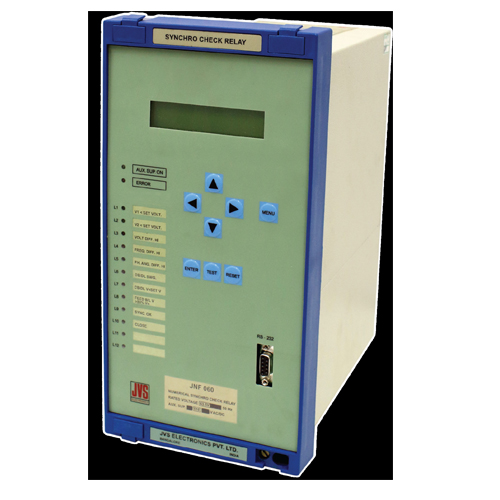
Numerical Check Synchronizing Relay -jnf 060
JVS Electronics Pvt Ltd offers a wide range of numerical check synchronizing relay -JNF 060.
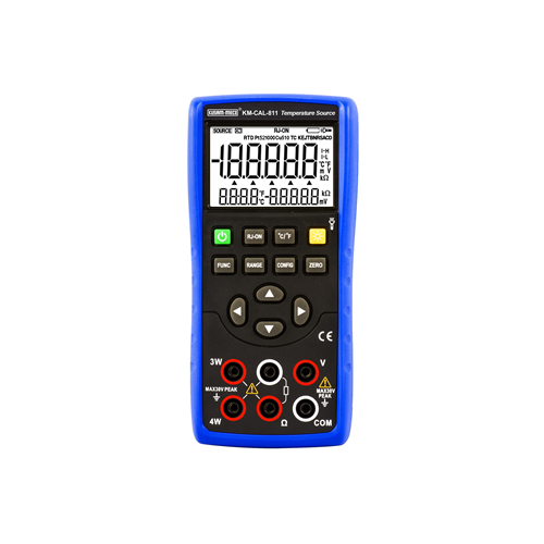
Kusam-meco” 1000v Dc Hand Held Digital Insulation Resistance Tester - Model- Km 372
Kusam-Meco has added a new hand-held digital insulation resistance tester cum digital multimeter for the convenience of electricians.
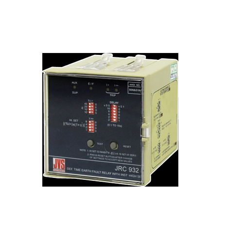
Single Pole Instantaneous /definite Time Earth Fault Relay -jrc 932
JVS Electronics Pvt Ltd offers a wide range of single pole instantaneous /definite time earth fault relay -JRC 932.


